
A speed transducer converts rotational or linear motion into an electrical signal — a pulse train from an encoder or proximity probe, or a voltage from a tachogenerator. That signal drives motor control loops, production-line speed, and safety interlocks. If the transducer’s output no longer matches true speed, every system that trusts it inherits the error, often without any obvious warning.
This guide explains how to calibrate speed transducer instruments the way an accredited laboratory does: by comparing their output against a traceable reference speed, capturing the result as error and uncertainty, and documenting it so you can defend the reading. It also corrects misconceptions in most quick guides—chiefly the idea that calibration is tweaking settings until the numbers look right.
| Quick answer: how do you calibrate a speed transducer?
1. Stabilize the transducer in a controlled environment and record its identity, type, and pulses-per-revolution or output scaling. 2. Apply known reference speeds from a traceable source — a reference speed standard or a calibrated frequency generator/counter (speed relates directly to frequency). 3. Test several points across the working range, ascending and descending, and record the transducer output against the reference as-found. 4. Calculate error at each point and evaluate the measurement uncertainty. 5. Adjust only if the unit is out of tolerance — after as-found data is recorded — then issue a calibration certificate and set the next-due date. |
How to Calibrate a Speed Transducer: Expert Guide
What a Speed Transducer Measures
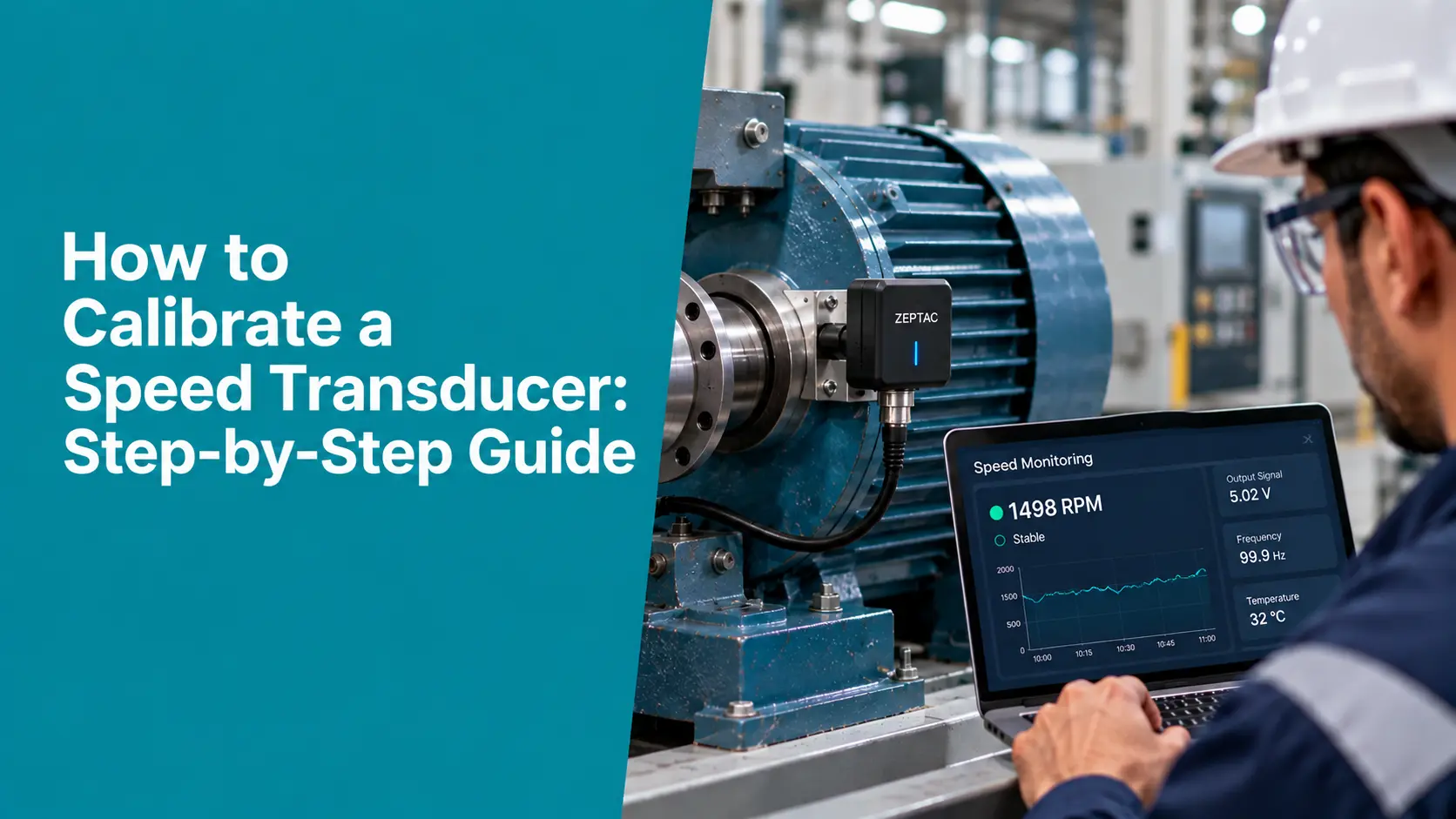
A speed transducer (also called a speed sensor or, for rotational types, a tachometer transducer) measures how fast something moves and outputs a proportional electrical signal. Common types include optical and magnetic encoders and proximity probes, which emit pulses at a rate proportional to speed, and tacho-generators, which output a voltage proportional to rotational speed. Sensors may be contact or non-contact, and measure rotational speed (in RPM) or linear speed (in m/s).
The key insight for calibration is that rotational speed lives in the time-frequency domain: speed in RPM relates directly to output frequency in hertz through the transducer’s pulses per revolution (for a pulse-output device, RPM = 60 × frequency ÷ pulses-per-rev). That relationship makes highly accurate, traceable calibration possible because frequency is one of the most precisely realized quantities in the SI system.
Calibration vs. Adjustment: The Distinction That Matters
The most common mistake is treating speed transducer calibration as a session of configuring settings until the display matches expectations. Setting a device’s scaling or “teaching” it a value is configuration, not calibration — and doing it before recording data erases the evidence calibration exists to capture.
Calibration is the documented comparison of the transducer’s output against a reference speed of known, traceable value, producing a statement of error and uncertainty.
Adjustment is the separate act of bringing an out-of-tolerance unit back within specification. Adjustment may follow calibration, but only after you record the “as-found” condition —because that as-found data tells you whether measurements taken since the last calibration can be trusted.
| Golden rule
Always record the as-found reading before touching any scaling, offset, or adjustment. Adjusting first erases the transducer’s history and invalidates reverse traceability for past results. |
What You Need (and What Won’t Do)
Because speed measurement is a time-frequency measurement, the reference must be a genuine, traceable speed or frequency standard — not a second uncalibrated sensor, and never the transducer under test acting as its own reference.
- Preferred — reference speed standard: a calibrated reference speed source — a precision speed-controlled motor or rate source whose speed is measured by a traceable reference tachometer/encoder — driving the transducer through its range.
- Alternative — frequency method: for pulse-output encoders, a calibrated frequency counter measures the output frequency (or a calibrated frequency generator injects a known equivalent), since speed maps directly to frequency.
- Also required: all reference equipment must carry current calibration traceable to the SI second (and, for linear speed, the meter) through a national metrology institute; a stable, low-vibration, EMI-controlled environment; and the transducer’s datasheet for range, scaling, and tolerance.
How to Calibrate Speed Transducer: Step-by-Step Procedure
- Inspect and stabilize. Inspect the transducer and cabling for damage, verify secure mechanical coupling and alignment, and record model, serial number, type, pulses-per-revolution or output scaling, and range. Allow any specified warm-up time for the electronics to stabilize.
- Zero / rest check. With the transducer at rest, confirm the output reads zero (or the correct rest state). A non-zero rest output points to an offset fault that will bias every reading.
- Choose test points. Select at least five points spread across the working range — low, mid, and high speed. Testing across the span exposes linearity errors a single mid-scale check would miss.
- Capture as-found data. At each point, set the reference speed (or equivalent frequency) and record the transducer’s output alongside the reference value, before any adjustment. For pulse devices, confirm the pulses-per-rev scaling is applied correctly.
- Run ascending, descending, and repeat. Approach each point by increasing and by decreasing speed, and repeat readings. Differences between directions or repeats reveal hysteresis and repeatability that a one-pass test hides.
- Calculate error and uncertainty. Compute error at each point as Error (%) = [(Transducer Reading − Reference) ÷ Reference] × 100, and evaluate the expanded measurement uncertainty for the calibration.
- Adjust if out of tolerance. Only if a point falls outside the transducer’s stated tolerance, adjust the scaling or offset per the manufacturer, then re-measure and record the “as-left” values.
- Document and certify. Issue a calibration certificate showing as-found and as-left data, the reference standards used with their traceability, environmental conditions, error, expanded uncertainty (typically k = 2, ~95% confidence), and the next-due date.
Two Ways to Establish the Reference Speed
Reference speed standard (comparison method)
A calibrated reference speed source physically drives the transducer at known speeds, and you compare its output to the reference across the range. This method exercises the whole measurement chain — sensor, coupling, and electronics — so it captures real-world effects like mechanical slip or misalignment. It is the right choice when the transducer’s installed behavior matters.
Frequency method (for pulse-output devices)
Because a pulse-output transducer’s speed maps to frequency, you can measure its output directly with a traceable frequency counter, or inject a traceable frequency to simulate a precise speed. This isolates the electronics and delivers very low uncertainty, but it does not test the mechanical coupling—so it complements, rather than replaces, a physical drive when coupling integrity is in question.
Common Challenges and How to Handle Them
- Electrical interference: Electromagnetic interference from nearby drives or wiring corrupts pulse and voltage signals; route cables away from noise sources, use shielded/twisted cabling, and ground properly before concluding the transducer is at fault.
- Mechanical misalignment: Poor coupling or misalignment between the transducer and the shaft introduces speed error and slip; verify mounting, couplings, and alignment per the manufacturer before calibrating.
- Environmental effects: Temperature, humidity, and vibration shift readings; calibrate within the specified operating conditions and record the environment on the certificate.
- Mistaking setup for calibration: Configuring the device’s scaling and calling it “calibrated” produces a confident but undocumented number; always compare against a traceable reference and record error and uncertainty.
Traceability and Measurement Uncertainty
A calibration result means nothing without traceability. A speed transducer calibration inherits metrological rigor only when its reference source or counter is traceable through an unbroken chain to a national standard — in India, the time-and-frequency standard maintained by CSIR-NPL, and internationally through NIST and the cesium-based definition of the second. For linear-speed devices, traceability also involves the meter.
Every reported value should carry an expanded measurement uncertainty evaluated in line with the GUM (Guide to the Expression of Uncertainty in Measurement), usually stated at a coverage factor of k = 2 (about 95% confidence). Contributions typically include the reference standard’s own uncertainty, transducer resolution and repeatability, the coupling or detection method, and environmental effects. A speed reading without an uncertainty statement is an assertion, not a measurement.
Calibration Interval and Records
A sensible default interval is once every 12 months, tightened for heavy use, harsh environments, or safety- and quality-critical speed measurements. The right interval is risk-based: weigh usage, the drift observed between past calibrations, and the consequence of an out-of-tolerance reading. Retain each certificate and the as-found/as-left history so drift can be trended over the transducer’s life — the data that justifies extending or shortening the interval.
Standards and Compliance Considerations
| Reference | What it governs |
| ISO/IEC 17025:2017 | Competence of testing and calibration laboratories — traceability, method validity, and measurement uncertainty for calibration. |
| GUM (JCGM 100) / VIM (JCGM 200) | How to evaluate and express measurement uncertainty, and the standard metrological vocabulary. |
| SI traceability (NPL India / NIST) | The unbroken chain from the reference standard to the national realization of the second (and the meter for linear speed). |
| NABL accreditation | In India, third-party recognition that a calibration laboratory is competent and its certificates are traceable. |
| IATF 16949 / 21 CFR Part 11 / ALCOA+ | Sector requirements for automotive and regulated users, including electronic-record integrity for calibration data. |
How Zeptac Helps
Knowing how to calibrate speed transducer devices correctly is one thing; proving it across an entire fleet of sensors, drives, and instruments, on schedule, is another. That is where Zeptac’s calibration platform earns its place:
- Calibration management (CalTac): CalTac holds every transducer’s calibration history, as-found/as-left records, reference-standard traceability, and certificates in one auditable system.
- Interval and recall control: automatic due-date tracking and escalations mean a sensor is never accidentally used past its interval.
- Audit-ready compliance: records are maintained to ISO/IEC 17025, 21 CFR Part 11, and ALCOA+ data-integrity principles, so audits become a search, not a scramble.
- Connected to the shop floor: calibration status connects to the same platform that monitors your rotating and moving equipment, so speed data is trusted only when the transducer behind it is in-date.
The result is not just a correctly calibrated speed transducer, but a documented, defensible traceability trail for every one you run.
Conclusion
Learning how to calibrate speed transducer instruments correctly comes down to a few disciplined habits: drive the transducer at traceable reference speeds rather than trusting its own display, record the as-found condition before any adjustment, test linearity and repeatability across the range, and report every result with its uncertainty. Done this way, speed transducer calibration turns a raw signal into a trustworthy measurement — and produces records that stand up to any auditor. When done by feel, every control loop and safety interlock downstream inherits that doubt.
| Keep every sensor calibrated, traceable, and audit-ready
Looking to digitize your calibration, testing, or validation processes? Zeptac’s CalTac platform automates due-date tracking, traceability, and certificate management so your laboratory and shop floor stay compliant and inspection-ready. Contact our team today to schedule a free demo. |
Frequently Asked Questions: How to Calibrate a Speed Transducer: A Complete Guide
Q1. How often should a speed transducer be calibrated?
Answer: A common default is once every 12 months, but the correct interval is risk-based. Calibrate more frequently for heavy use, harsh environments, or safety- and quality-critical measurements, and use the drift observed between past calibrations to justify tightening or extending the interval.
Q2. What is the difference between calibrating and adjusting a speed transducer?
Answer: Calibration compares the transducer’s output against a traceable reference speed and reports error and uncertainty. Adjustment corrects an out-of-tolerance unit’s scaling or offset. Always record the as-found reading before any adjustment, or you lose the history that shows whether earlier measurements were valid.
Q3. What reference equipment do I need to calibrate a speed transducer?
Answer: You need a traceable reference speed standard (a precision speed source with a calibrated reference tachometer or encoder) or, for pulse-output devices, a calibrated frequency counter or generator. The reference must be traceable to the SI second, and the device under test can never be its own reference.
Q4. Can I calibrate a speed transducer without specialized equipment?
Answer: No. Reliable calibration requires a traceable reference speed source or frequency standard. Improvised setups—an uncalibrated handheld tachometer or a stopwatch—cannot provide the traceability and uncertainty a defensible calibration needs.
Q5. What causes inaccurate speed transducer readings?
Answer: Common causes include electromagnetic interference, mechanical misalignment or coupling slip, environmental drift, incorrect pulses-per-revolution scaling, and — often overlooked — an out-of-calibration reference standard. Rule out the reference and the installation before condemning the transducer.
Q6. Do I need an accredited lab, or can I calibrate in-house?
Answer: Either is possible if you handle traceability and uncertainty correctly. In-house calibration needs a traceable calibrated reference, a documented method, and competent staff. Where third-party assurance is required — for audits or accreditation — a NABL-accredited laboratory issues certificates recognized against ISO/IEC 17025.
Q7. Are there regulatory requirements for speed transducer calibration?
Answer: It depends on the sector. Automotive suppliers work under IATF 16949, regulated manufacturers under 21 CFR Part 11 and ALCOA+, and many quality systems reference ISO 9001. The common thread is documented, traceable calibration to ISO/IEC 17025 with a stated measurement uncertainty.