
A gauge block sitting on a granite surface plate in a 26 °C workshop is not the length stamped on its side. A one-meter steel artifact measured six degrees above the reference temperature reads roughly 69 µm long — enough to reject good parts or pass bad ones on a tight tolerance. Dimensional metrology calibration is how manufacturers close that gap: comparing length, angle, and form instruments against traceable standards, correcting for the physics, and stating how much they can trust the result.
This guide covers the reference temperature convention that underpins dimensional metrology, how the common instruments are actually verified, the error sources that hide in the setup, and what makes a dimensional metrology certificate defensible in an audit.
| At a glance
Dimensional metrology calibration compares length, angle, and form measuring instruments against traceable reference standards to determine their error and uncertainty. All results refer to the standard reference temperature of 20 °C, as defined in ISO 1:2022, so measurements taken at other temperatures must be corrected. Gauge blocks under ISO 3650 provide the reference for most instruments; CMMs are verified against calibrated test lengths under ISO 10360, and conformity statements follow the decision rules of ISO 14253-1 — commonly simple 4:1 acceptance, where uncertainty is no more than 25% of the tolerance. |
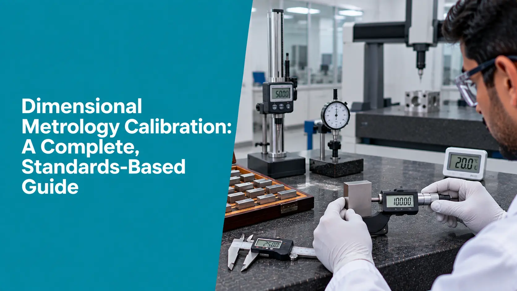
Dimensional Metrology Calibration: A Complete, Standards-Based Guide
The 20 °C Rule That Everything Depends On
The meter is defined by the distance light travels in a vacuum, so the unit itself is independent of temperature. Physical objects are not. Steel expands and contracts, so a dimension only means something when you state the temperature it applies to.
That is why ISO 1:2022 fixes the standard reference temperature at 20 °C, interpreted on the ITS-90 scale. Every dimension on an engineering drawing, every gauge block value, and every calibration certificate refers to the object’s size at 20 °C. The convention has been international since the CIPM adopted it in April 1931.
Measurements almost never happen at exactly 20 °C, so a correction is required:
Thermal expansion correctionΔL = L × α × ( t − 20 °C ) For steel gauge blocks, ISO 3650 gives a coefficient of thermal expansion of (11.5 ± 1) × 10⁻⁶ per °C — about 11.5 µm per meter for every degree away from reference. Stainless steel is closer to 16 × 10⁻⁶, and aluminum to 23 × 10⁻⁶. |
Two consequences follow:
- If the workpiece and the instrument are different materials, they expand at different rates and a differential correction is needed.
- If the correction is not applied exactly, the uncertainty must be carried in the uncertainty budget. ISO 1 is explicit on this point.
Precision at the top end is remarkable: the 2022 edition clarified that 20 °C is the ITS-90 value rather than the thermodynamic one, a difference of 2.8 mK — worth about 0.03 µm per meter in steel.
Calibration, Verification, and Adjustment Are Not the Same
Three operations get blurred together across dimensional metrology, and the confusion costs real money.
- Calibration establishes the relationship between the instrument’s indication and a reference value, with its uncertainty. It produces information, not a modified instrument.
- Verification compares that information against a specification — typically a maximum permissible error (MPE) — and yields a conformity statement.
- Adjustment physically alters the instrument so it reads closer to the correct value. Separate operation invalidates the as-found data if done first.
The order matters. Record what the instrument read on arrival, then adjust only if needed and authorized, then re-calibrate to capture the as-left condition. Skip the as-found step, and nobody can answer the question every auditor asks: were the parts this gauge accepted last quarter actually in tolerance?
Where Dimensional Metrology Calibration Goes Wrong
The failure modes are consistent:
- Ignoring temperature — measuring at ambient and reporting as though it were 20 °C.
- No soak time — a gauge block handled bare-handed for thirty seconds is no longer at room temperature.
- Abbe offset in the setup — the measuring scale not in line with the dimension being measured.
- Wrong gauge block grade — using inspection-grade blocks where calibration-grade is required.
- Conformity statements with no decision rule — declaring PASS without defining how uncertainty was handled at the tolerance limit.
- Contact force and probe effects — measuring soft or thin-walled parts without accounting for deformation.
Gauge Blocks: The Reference Beneath Everything
Nearly every dimensional metrology instrument in a factory traces back to gauge blocks. ISO 3650:1998 specifies them from 0.5 mm to 1000 mm in four grades. Note that grade 00 was withdrawn in the 1998 revision — older sets and older documentation still reference it.
|
Grade |
Designation |
Typical use |
|
K |
Calibration grade | Reference masters held by calibration laboratories; used to calibrate other blocks |
|
0 |
Toolroom grade |
Setting comparators; calibrating micrometers and dial indicators |
|
1 |
Inspection grade |
First-article inspection, CMM artifact checks, fixture setting |
|
2 |
Workshop grade | General shop-floor checking and setting |
Blocks are calibrated by mechanical comparison against a higher-grade master on a gauge block comparator — the method EURAMET cg-2 covers — or by interferometry at national-laboratory level. Handle them with gloves or tongs, wring them properly, and never leave them wrung together for long periods.
Abbe’s Principle and the Errors That Hide in the Setup
Ernst Abbe stated the rule in the nineteenth century: to make a good measurement, the measurement standard must lie on the same line as the dimension being checked. When the scale is offset from the measurement axis, any small rotation in the mechanism turns into a length error:
e = d × sin θ
where d is the offset, known as the Abbe length. This is why a micrometer—whose screw sits in line with the measured dimension—is inherently more accurate than a caliper, whose scale is offset from the jaws. It also explains why measuring at the tip of caliper jaws gives worse results than measuring deep in the throat.
Dimensional metrology has other setup-driven errors worth naming too: cosine error from misalignment, elastic deformation under contact force, parallax on analog scales, and dirt or burrs on measuring faces.
How Common Instruments Are Verified
Dimensional metrology calibration spans a wide range of instruments, each with its own reference artifact and characteristics to check:
| Instrument | Reference standard/artefact | Key characteristics checked |
| Calipers (ISO 13385-1) | Gauge blocks, caliper checker | Partial and full surface contact error, jaw parallelism, MPE conformity |
| Micrometers (ISO 3611) | Gauge blocks, optical flats | Error of indication across range, anvil flatness and parallelism |
| Dial indicators/gauges | Indicator calibration tester | Error over range, repeatability, hysteresis, reversal error |
| Height and depth gauges | Gauge blocks, step gauges | Linearity across range, squareness to base |
| CMMs (ISO 10360) | Calibrated test lengths — gauge blocks, step gauges, ball bars, laser interferometers | Length measurement error E₀, probing error, against stated MPE |
| Surface plates | Electronic level, autocollimator | Flatness across the working surface |
For CMMs specifically, ISO 10360-2 defines acceptance and reverification testing using bidirectional length measurements over calibrated test lengths. The artifact’s own calibration uncertainty must be factored into the result — a point routinely overlooked.
Decision Rules and Measurement Uncertainty
A measured error sitting right on the MPE is not a pass or a fail until you say how uncertainty was handled — a core discipline of dimensional metrology. In the GPS framework, ISO 14253-1 provides the default decision rules, ISO 14253-5 covers uncertainty in verification testing of indicating instruments, and ISO/TR 14253-6 covers alternatives.
In practice, calibrating instruments such as calipers uses a simple 4:1 acceptance criterion: conformity can be assessed when the measurement uncertainty is no more than 25% of the tolerance. A worked example from a 0–150 mm digital caliper gives an expanded uncertainty of about ±1.2 µm against a ±20 µm tolerance — around 6%, comfortably inside the rule.
Whatever rule applies, it must be agreed in advance and stated on the certificate, in line with ISO/IEC 17025 clauses 7.1.3 and 7.8.6.
Compliance and Certificate Content
ISO/IEC 17025 governs competence, traceability, and reporting, with NABL operating the accreditation scheme in India and ILAC-P14 setting uncertainty policy for accredited laboratories. A defensible dimensional metrology certificate should carry:
- Instrument identification, type, range, and serial number
- Reference standards used and their traceability
- Ambient temperature during measurement, and any thermal correction applied
- As-found and as-left results at each point
- Expanded measurement uncertainty and coverage factor
- The decision rule, where a conformity statement is given
- Calibration date and, where requested, the due date
Best Practices Worth Enforcing
A few habits separate a controlled dimensional metrology calibration program from a reactive one:
- Soak instruments and artifacts in the measurement room before use — hours for large steel parts, not minutes.
- Handle gauge blocks and masters with gloves or tongs; body heat is a measurable error source.
- Log ambient temperature with every calibration, not just when it looks unusual.
- Calibrate across the working range, including the sizes that actually matter in production.
- Set intervals from drift history and measurement risk rather than a default twelve months.
- Assess the impact of any out-of-tolerance result on everything measured since the previous calibration.
Digital Transformation, AI, and IoT
Manual dimensional metrology calibration breaks in two places: the uncertainty arithmetic and the records. Modern platforms fix both. Data flows straight from comparators, CMMs, and digital indicators, removing transcription error. Software applies the thermal correction and the full uncertainty budget identically every time, and applies the agreed decision rule consistently. IoT-connected environmental sensors log temperature and humidity for each calibration event, while drift analytics support risk-based intervals—flagging a gauge trending toward its limit before it starts passing bad parts.
How Zeptac Helps in Dimensional Metrology Calibration
Zeptac’s CalTac calibration management software includes a dedicated Dimension Metrology module built for dimensional metrology work. It automates Type A and Type B measurement uncertainty calculations, instantly generates ISO/IEC 17025- and NABL-ready certificates, and maintains complete instrument and reference-standard records so traceability is always demonstrable. Internal audit tools mapped to ISO 17025 clauses and NABL quality-document control keep the laboratory inspection-ready, and InstaCertify turns finished measurements into issued certificates immediately.
In practice:
- A calibration laboratory issues caliper, micrometer, and gauge-block certificates with automated uncertainty budgets, cutting turnaround from hours to minutes.
- A manufacturer tracks the calibration status of thousands of gauges across plants and blocks production use of anything overdue.
- A quality manager in a testing laboratory pulls a gauge’s complete as-found/as-left drift history during an audit in seconds, not hours.
Where This Is Heading
Expect wider use of non-contact and optical measurement, in-line metrology feeding directly into process control, and CMM data streaming into cloud quality systems. Temperature-compensated dimensional metrology is becoming standard rather than exceptional, and drift analytics are steadily replacing fixed calendar intervals with risk-based ones.
Conclusion
Sound dimensional metrology calibration comes down to four disciplines: respect the 20 °C reference and correct for temperature, keep calibration separate from verification and adjustment, understand the setup errors that Abbe’s principle explains, and state a complete uncertainty budget with an agreed decision rule on every certificate. Software that automates the arithmetic and the documentation turns an error-prone manual process into one that holds up under any audit.
Ready to digitize your calibration laboratory?Zeptac’s CalTac platform automates uncertainty calculations, applies your decision rules consistently, and generates ISO/IEC 17025- and NABL-ready certificates in minutes. |
Frequently Asked Questions for Dimensional Metrology Calibration
Q1. What is dimensional metrology calibration?
Answer: It is the comparison of length, angle, and form measuring instruments — calipers, micrometers, gauge blocks, height gauges, CMMs — against traceable reference standards to determine their error and the uncertainty of that determination.
Q2. Why is 20 °C the reference temperature?
Answer: Because objects expand and contract, a dimension is only unambiguous when its temperature is stated. ISO 1:2022 fixes the standard reference temperature at 20 °C, a convention adopted internationally by the CIPM in 1931.
Q3. How do you correct a temperature measurement?
Answer: Use ΔL = L × α × (t − 20 °C). For steel gauge blocks, ISO 3650 gives α as (11.5 ± 1) × 10⁻⁶ per °C, so a one-meter steel part measured at 26 °C reads about 69 µm long.
Q4. What are gauge block grades and which do I need?
Answer: ISO 3650 defines grades K, 0, 1, and 2. Grade K is the calibration master, grade 0 suits toolroom and comparator work, grade 1 is for general inspection, and grade 2 is for shop-floor use.
Q5. What is Abbe error?
Answer: The length error introduced when the measuring scale is misaligned with the dimension being measured. It equals d × sin θ, where d is the offset. This is why micrometers are inherently more accurate than calipers.
Q6. What techniques are used in dimensional metrology calibration?
Answer: Mechanical comparison against gauge blocks and step gauges; laser interferometry for the highest accuracy; artifact-based verification for CMMs under ISO 10360; and optical or vision systems for profiles and non-contact work.
Q7. How often should dimensional metrology instruments be calibrated?
Answer: There is no universal interval. Base it on drift history, usage intensity, and the risk carried by the measurement. Many organizations start at 12 months and tighten or relax the interval once they have drift data.